Condensing Boilers
Wall Type Condensing Boilers
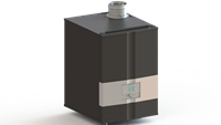
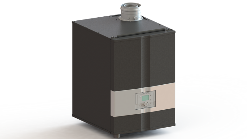
WT-SS Series
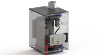
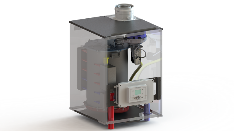
- High efficiency with Premix condensation technology and micro-flame metal fiber coated steel burner,
- High performance and long-lasting durability with expanded surface area and sheet thickness in the stainless steel heat exchanger,
- Heat exchanger protection with magnetic residue protection integrated in the boiler,
- Enhanced combustion efficiency with flash back flap,
- Low energy consumption with the modulating primary circuit pump integrated to the boiler with capacities 45-50-55-60-65 kW,
- 12 different large capacity options as 45, 50, 55, 60, 65, 80, 90, 100, 110, 115, 125, 150 in single boiler
- Wide thermal capacity option up to 2,400 kW, thanks to the cascade connection of 16 boilers in cascade systems
- Maximum air and water tightness with hermetic case,
- Energy saving through 5:1 modulating operation,
- Illuminated LCD panel for ease of use,
- Daily and weekly operation schedule can be programmed,
- Preparing summer and winter seasonal heat program,
- Option of use with natural gas and LPG,
- Operation at lower noise values,
- Frost protection feature,
- Eco-friendly heating systems with low NOx and CO emission rates,
| TECHNICAL SPECIFICATIONS | Unit | WT-SS 45 |
WT-SS 50 |
WT-SS 55 |
WT-SS 60 |
WT-SS 65 |
WT-SS 80 |
WT-SS 90 |
WT-SS 100 |
WT-SS 110 |
WT-SS 115 |
WT-SS 125 |
WT-SS 150 |
|||||
|---|---|---|---|---|---|---|---|---|---|---|---|---|---|---|---|---|---|---|
| Thermal Capacity | ||||||||||||||||||
| Maximum Heating Capacity | kW | 45 | 50 | 55 | 60 | 65 | 80 | 90 | 100 | 110 | 115 | 125 | 143 | |||||
| Minimum Heating Capacity | kW | 9,72 | 10,8 | 11,8 | 12,9 | 14 | 14,15 | 14,18 | 14,27 | 19,9 | 19,9 | 20 | 20 | |||||
| Maximum Heat Output (80°C / 60°C) | kW | 43,7 | 48,6 | 53,3 | 58,2 | 63.2 | 77,8 | 87,5 | 97,2 | 106,9 | 111,7 | 121,4 | 138,5 | |||||
| Minimum Heat Output (80°C / 60°C) | kW | 9,5 | 10,5 | 11,5 | 12,6 | 13,7 | 13,8 | 13,8 | 13,9 | 19,4 | 19,4 | 19,5 | 19,5 | |||||
| Maximum Heat Output (70°C / 50°C) | kW | 45,6 | 50,7 | 55,5 | 60,7 | 65,9 | 81,1 | 91,3 | 101,4 | 111,5 | 116,4 | 126,5 | 144,5 | |||||
| Minimum Heat Output (70°C / 50°C) | kW | 10,0 | 11,1 | 12,1 | 13,3 | 14,4 | 14,6 | 14,6 | 14,7 | 20,4 | 20,4 | 20,5 | 20,5 | |||||
| Maximum Heat Output (50°C / 30°C) | kW | 47,6 | 52,8 | 57,8 | 63,2 | 68,6 | 84,4 | 95 | 105,5 | 116,1 | 121 | 131,5 | 150,4 | |||||
| Minimum Heat Output (50°C / 30°C) | kW | 10,4 | 11,6 | 12,7 | 13,9 | 15,1 | 15,3 | 15,3 | 15,4 | 21,3 | 21,3 | 21,5 | 21,5 | |||||
| Thermal Efficiency | ||||||||||||||||||
| Efficiency @ Pmax. (80°C / 60°C) | % | 97,1 | 97,2 | 96,9 | 97,1 | 97,2 | 97,3 | 97,2 | 97,2 | 97,2 | 97,1 | 97,1 | 97 | |||||
| Efficiency @ Pmin. (80°C / 60°C) | % | 97,6 | 97,6 | 97,9 | 97,9 | 97,9 | 97,5 | 97,3 | 97,4 | 97,5 | 97,5 | 97,5 | 97,5 | |||||
| Efficiency @ Pmax. (70°C / 50°C) | % | 101,4 | 101,4 | 101,0 | 101,2 | 101,4 | 101,4 | 101,4 | 101,4 | 101,4 | 101,2 | 101,2 | 101,0 | |||||
| Efficiency @ Pmin. (70°C / 50°C) | % | 102,6 | 102,6 | 102,9 | 102,9 | 102,9 | 102,8 | 102,6 | 102,7 | 102,3 | 102,3 | 102,5 | 102,5 | |||||
| Efficiency @ Pmax. (50°C / 30°C) | % | 105,8 | 105,5 | 105,1 | 105,4 | 105,5 | 105,5 | 105,6 | 105,5 | 105,5 | 105,2 | 105,2 | 105,2 | |||||
| Efficiency @ Pmin. (50°C / 30°C) | % | 107,2 | 107,5 | 107,9 | 107,9 | 107,9 | 108,1 | 107,9 | 107,9 | 107 | 107 | 107,5 | 107,5 | |||||
| Efficiency @ %30 (30°C) | % | 108,1 | 108,2 | 108,3 | 108,3 | 108,4 | 108,2 | 108,2 | 108,3 | 108,1 | 108,1 | 108,3 | 108,4 | |||||
| Domestic Hot Water Circuit | ||||||||||||||||||
| Temperature adjustment range with external storage tank usage | °C | 10-65 | 10-65 | 10-65 | 10-65 | 10-65 | 10-65 | 10-65 | 10-65 | 10-65 | 10-65 | 10-65 | 10-65 | |||||
| Central Heating Circuit | ||||||||||||||||||
| Maximum Operating Temperature | °C | 90 | 90 | 90 | 90 | 90 | 90 | 90 | 90 | 90 | 90 | 90 | 90 | |||||
| Water Volume | L | 5 | 5 | 5 | 5 | 5 | 6 | 6 | 7 | 7 | 8 | 8 | 9 | |||||
| Maximum Operating Pressure | bar | 6 | 6 | 6 | 6 | 6 | 6 | 6 | 6 | 6 | 6 | 6 | 6 | |||||
| Minimum Operating Pressure | bar | 1 | 1 | 1 | 1 | 1 | 1 | 1 | 1 | 1 | 1 | 1 | 1 | |||||
| Water Resistance ΔT = 20 °C | bar | 260 | 270 | 290 | 300 | 310 | 360 | 370 | 390 | 340 | 360 | 380 | 410 | |||||
| Gas Specifications | ||||||||||||||||||
| Gaz Type | - | G20-G31 | G20-G31 | G20-G31 | G20-G31 | G20-G31 | G20-G31 | G20-G31 | G20-G31 | G20-G31 | G20-G31 | G20-G31 | G20-G31 | |||||
| Gas Inlet Pressure (G20) | mbar | 20 | 20 | 20 | 20 | 20 | 20 | 20 | 20 | 20 | 20 | 20 | 20 | |||||
| Gas Inlet Pressure (G31) | mbar | 37 | 37 | 37 | 37 | 37 | 37 | 37 | 37 | 37 | 37 | 37 | 37 | |||||
| Maximum Gas Consumption | Nm³/h | 4,69 | 5,21 | 5,73 | 6,25 | 6,78 | 8,34 | 9,38 | 10,42 | 11,47 | 12 | 13,03 | 14,91 | |||||
| Minimum Gas Consumption | Nm³/h | 1,01 | 1,13 | 1,23 | 1,34 | 1,46 | 1,48 | 1,48 | 1,49 | 2,07 | 2,07 | 2,08 | 2,08 | |||||
| Combustion Specifications | ||||||||||||||||||
| Maximum Flue Gas Temperature (50°C / 30°C) | °C | 52,4 | 52,6 | 54,7 | 55,2 | 55,3 | 55,7 | 56,2 | 57,5 | 57,1 | 56,2 | 57,2 | 57,5 | |||||
| Maximum Flue Gas Temperature (70°C / 50°C) | °C | 63,7 | 65,6 | 68,0 | 67,9 | 68,1 | 68,6 | 69,1 | 71,3 | 72,7 | 72, | 68,9 | 69,8 | |||||
| Maximum Flue Gas Temperature (80°C / 60°C) | °C | 69,4 | 72,1 | 74,6 | 74,2 | 74,5 | 75,1 | 75,6 | 78,2 | 80,5 | 81,2 | 80,6 | 82 | |||||
| NOx Emission Class (EN 15502-1+A1) | - | 6 | 6 | 6 | 6 | 6 | 6 | 6 | 6 | 6 | 6 | 6 | 6 | |||||
| Electrical Specifications | ||||||||||||||||||
| Electrical Supply | V / Hz | 230/50 | 230/50 | 230/50 | 230/50 | 230/50 | 230/50 | 230/50 | 230/50 | 230/50 | 230/50 | 230/50 | 230/50 | |||||
| Protection Class | IP | X4D | X4D | X4D | X4D | X4D | X4D | X4D | X4D | X4D | X4D | X4D | X4D | |||||
| Energy Consumption | W | 62 | 65 | 70 | 80 | 90 | 110 | 120 | 130 | 140 | 170 | 220 | 260 | |||||
| Fuse Current | A | 6 | 6 | 6 | 6 | 6 | 6 | 6 | 6 | 6 | 6 | 6 | 6 | |||||
| Circuit Specifications | ||||||||||||||||||
| Gas Connection Diameter | inch | 3/4 | 3/4 | 3/4 | 3/4 | 3/4 | 3/4 | 3/4 | 3/4 | 3/4 | 3/4 | 3/4 | 3/4 | |||||
| Central Heating Circuit Inlet/Outlet Diameter | inch | 3/4 | 3/4 | 1 | 1 | 1 | 1 1/2 | 1 1/2 | 1 1/2 | 1 1/2 | 1 1/2 | 1 1/2 | 1 1/2 | |||||
| General Specifications | ||||||||||||||||||
| Net Weight | kg | 60 | 60 | 65 | 65 | 65 | 75 | 75 | 75 | 80 | 80 | 80 | 80 | |||||
| Flue Diameter (Ø) | mm | 60/100 | 60/100 | 80/125 | 80/125 | 80/125 | 100/150 | 100/150 | 100/150 | 100/150 | 100/150 | 100/150 | 100/150 | |||||
| G 20 Natural Gas, G 31 LPG | ||||||||||||||||||
| MODEL | W (mm) |
H (mm) |
D (mm) |
C1 (mm) |
C2 (mm) |
C3 (mm) |
C4 (mm) |
C5 (mm) |
C6 (mm) |
C7 (mm) |
C8 (mm) |
|---|---|---|---|---|---|---|---|---|---|---|---|
| WT-SS 45 | 450 | 756 | 380 | 123 | 342 | 175 | 205 | 127 | 63 | 170 | 107 |
| WT-SS 50 | 450 | 756 | 380 | 123 | 342 | 175 | 225 | 127 | 85 | 170 | 107 |
| WT-SS 55 | 465 | 820 | 465 | 54 | 354 | 260 | 224 | 68 | 68 | 232 | 118 |
| WT-SS 60 | 465 | 820 | 465 | 54 | 354 | 260 | 229 | 68 | 68 | 232 | 118 |
| WT-SS 65 | 465 | 820 | 465 | 54 | 354 | 37 | 301 | 68 | 68 | 232 | 118 |
| WT-SS 80 | 546 | 670 | 640 | 90 | 470 | 500 | 74 | 450 | 523 | 104 | 139 |
| WT-SS 90 | 546 | 670 | 640 | 90 | 470 | 500 | 74 | 450 | 523 | 104 | 139 |
| WT-SS 100 | 546 | 670 | 640 | 90 | 470 | 500 | 74 | 450 | 523 | 104 | 139 |
| WT-SS 110 | 546 | 750 | 640 | 90 | 470 | 500 | 74 | 450 | 523 | 104 | 139 |
| WT-SS 115 | 546 | 750 | 640 | 90 | 470 | 500 | 74 | 450 | 523 | 104 | 139 |
| WT-SS 125 | 546 | 750 | 640 | 90 | 470 | 500 | 74 | 450 | 523 | 104 | 139 |
| WT-SS 150 | 546 | 750 | 640 | 90 | 470 | 500 | 74 | 450 | 523 | 104 | 139 |
