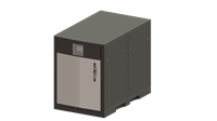
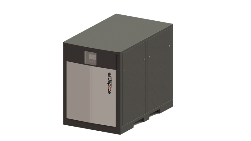
Ecodense
Floor Type Condensing Boilers

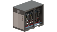
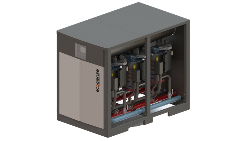
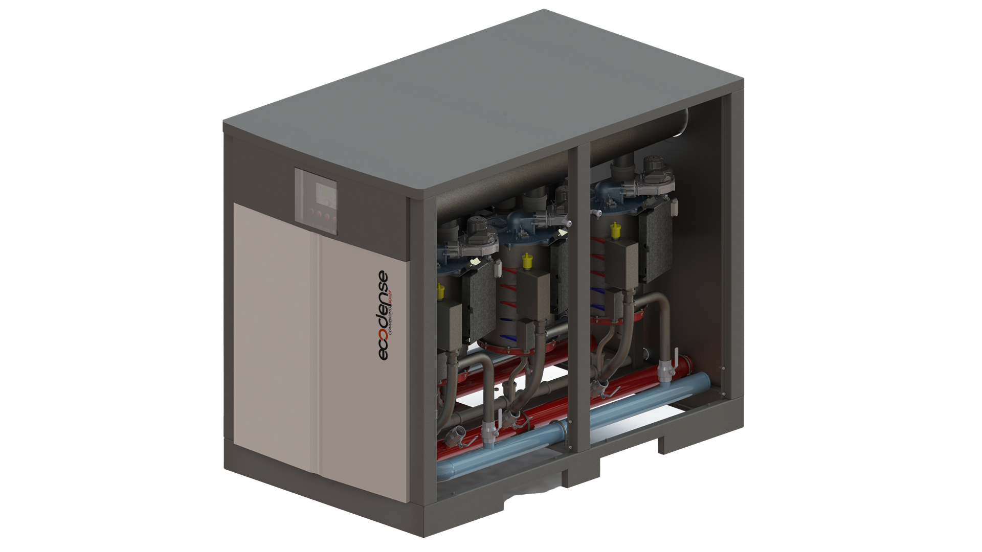
CELL-CONDENSE-SS Series
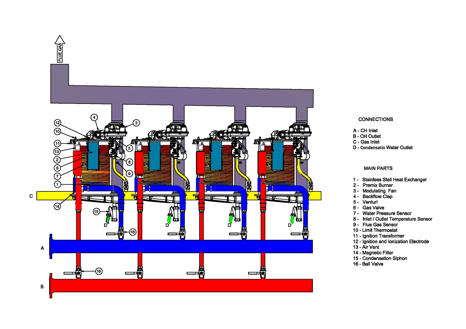
- High efficiency with Premix condensation technology and micro-flame metal fiber coated steel burner,
- High performance and long-lasting durability with expanded surface area and sheet thickness in the stainless steel heat exchanger,
- Heat exchanger protection with magnetic residue protection integrated in the boiler,
- Low back pressure thanks to the collector structure,
- Trouble-free operation of other boilers in case of failure of one or more boilers,
- 11 different large capacity options as 290,420,560,700,840,1000,1120,1260,1400,1540,1680, in single boiler,
- Wide thermal capacity option up to 16,800 kW, thanks to the cascade connection of 16 boilers in cascade systems,
- Energy saving through 5:1 modulating operation,
- Illuminated LCD panel for ease of use,
- Daily and weekly operation schedule can be programmed,
- Preparing summer and winter seasonal heat program,
- Option of use with natural gas and LPG,
- Operation at lower noise values,
- Frost protection feature,
- Eco-friendly heating systems with low NOx and CO emission rates,
| TECHNICAL SPECIFICATIONS | UNIT | CELL CONDENSE 290 |
CELL CONDENSE 420 |
CELL CONDENSE 560 |
CELL CONDENSE 700 |
CELL CONDENSE 840 |
CELL CONDENSE 1000 |
CELL CONDENSE 1120 |
CELL CONDENSE 1260 |
CELL CONDENSE 1400 |
CELL CONDENSE 1540 |
CELL CONDENSE 1680 |
|||||||||
|---|---|---|---|---|---|---|---|---|---|---|---|---|---|---|---|---|---|---|---|---|---|
| Thermal Capacity | |||||||||||||||||||||
| Maximum Heating Capacity | kW | 280 | 405 | 533 | 676 | 800 | 964 | 1080 | 1217 | 1371 | 1500 | 1641 | |||||||||
| Minimum Heating Capacity | kW | 20 | 20 | 20 | 20 | 20 | 20 | 20 | 20 | 20 | 20 | 20 | |||||||||
| Maximum Heat Output (80°C / 60°C) | kW | 270 | 392 | 515 | 653 | 774 | 931 | 1041 | 1179 | 1321 | 1451 | 1590 | |||||||||
| Minimum Heat Output (80°C / 60°C) | kW | 19,5 | 19,5 | 19,5 | 19,5 | 19,5 | 19,5 | 19,5 | 19,5 | 19,5 | 19,5 | 19,5 | |||||||||
| Maximum Heat Output (50°C / 30°C) | kW | 294 | 426 | 560 | 710 | 840 | 1014 | 1135 | 1280 | 1440 | 1578 | 1725 | |||||||||
| Minimum Heat Output (50°C / 30°C) | kW | 21,5 | 21,5 | 21,5 | 21,5 | 21,5 | 21,5 | 21,5 | 21,5 | 21,5 | 21,5 | 21,5 | |||||||||
| Thermal Efficiency | |||||||||||||||||||||
| Efficiency @ Pmax. (80°C / 60°C) | % | 96,4 | 96,8 | 96,6 | 96,6 | 96,8 | 96,6 | 96,4 | 96,9 | 96,4 | 96,7 | 96,9 | |||||||||
| Efficiency @ Pmin. (80°C / 60°C) | % | 97,5 | 97,5 | 97,5 | 97,5 | 97,5 | 97,5 | 97,5 | 97,5 | 97,5 | 97,5 | 97,5 | |||||||||
| Efficiency @ Pmax. (50°C / 30°C) | % | 105 | 105,2 | 105,1 | 105 | 105 | 105,2 | 105,1 | 105,2 | 105 | 105,2 | 105,1 | |||||||||
| Efficiency @ Pmin. (50°C / 30°C) | % | 107,5 | 107,5 | 107,5 | 107,5 | 107,5 | 107,5 | 107,5 | 107,5 | 107,5 | 107,5 | 107,5 | |||||||||
| Efficiency @ %30 (30°C) | % | 107,2 | 107,2 | 107,1 | 107,1 | 107,3 | 107,2 | 107,2 | 107,2 | 107,2 | 107,2 | 107,2 | |||||||||
| Domestic Hot Water Circuit | |||||||||||||||||||||
| Temperature adjustment range with domestic hot water | °C | 30-65 | 30-65 | 30-65 | 30-65 | 30-65 | 30-65 | 30-65 | 30-65 | 30-65 | 30-65 | 30-65 | |||||||||
| Central Heating Circuit | |||||||||||||||||||||
| Maximum Operating Temperature | °C | 90 | 90 | 90 | 90 | 90 | 90 | 90 | 90 | 90 | 90 | 90 | |||||||||
| Water Volume | L | 21 | 32 | 41 | 51 | 60 | 70 | 79 | 90 | 99 | 108 | 117 | |||||||||
| Maximum Operating Pressure | bar | 6 | 6 | 6 | 6 | 6 | 6 | 6 | 6 | 6 | 6 | 6 | |||||||||
| Minimum Operating Pressure | bar | 1 | 1 | 1 | 1 | 1 | 1 | 1 | 1 | 1 | 1 | 1 | |||||||||
| Water Resistance ΔT = 20 °C | mbar | 360 | 360 | 380 | 370 | 380 | 420 | 420 | 420 | 420 | 420 | 420 | |||||||||
| Gas Specifications | |||||||||||||||||||||
| Gas Type | - | G20-G31 | G20-G31 | G20-G31 | G20-G31 | G20-G31 | G20-G31 | G20-G31 | G20-G31 | G20-G31 | G20-G31 | G20-G31 | |||||||||
| Gas Inlet Pressure (G20) | mbar | 20 | 20 | 20 | 20 | 20 | 20 | 20 | 20 | 20 | 20 | 20 | |||||||||
| Maximum gas consumption | Nm³/h | 29,19 | 42,22 | 55,56 | 70,47 | 83,39 | 100,49 | 112,58 | 126,86 | 142,92 | 156,36 | 171,06 | |||||||||
| Minimum gas consumption | Nm³/h | 2,08 | 2,08 | 2,08 | 2,08 | 2,08 | 2,08 | 2,08 | 2,08 | 2,08 | 2,08 | 2,08 | |||||||||
| Combustion Specifications | |||||||||||||||||||||
| Maximum Flue Gas Temperature (50°C / 30°C) | °C | 50 | 50 | 50 | 50 | 50 | 50 | 50 | 50 | 50 | 50 | 50 | |||||||||
| Maximum Flue Gas Temperature (80°C / 60°C) | °C | 75 | 75 | 75 | 75 | 75 | 75 | 75 | 75 | 75 | 75 | 75 | |||||||||
| NOx Emission Class (EN 15502-1+A1) | - | 6 | 6 | 6 | 6 | 6 | 6 | 6 | 6 | 6 | 6 | 6 | |||||||||
| Electrical Specifications | |||||||||||||||||||||
| Electrical Supply | V / Hz | 230/50 | 230/50 | 230/50 | 230/50 | 230/50 | 230/50 | 230/50 | 230/50 | 230/50 | 230/50 | 230/50 | |||||||||
| Protection Class | IP | X4D | X4D | X4D | X4D | X4D | X4D | X4D | X4D | X4D | X4D | X4D | |||||||||
| Energy Consumption | W | 640 | 960 | 1280 | 1600 | 1920 | 2240 | 2560 | 2880 | 3200 | 3520 | 3840 | |||||||||
| Fuse Current | A | 6 | 6 | 6 | 6 | 6 | 6 | 6 | 6 | 6 | 6 | 6 | |||||||||
| Heat Exchanger | |||||||||||||||||||||
| Heat Exchanger Quantity | adet | 2 | 3 | 4 | 5 | 6 | 7 | 8 | 9 | 10 | 11 | 12 | |||||||||
| Circuit Specifications | |||||||||||||||||||||
| Gas Connection Diameter | inch | 1 1/2" | 2" | 2" | 2 1/2" | 2 1/2" | 2 1/2" | 2 1/2" | 2 1/2" | 2 1/2" | 2 1/2" | 2 1/2" | |||||||||
| Central Heating Circuit Inlet/Outlet Diameter | inch | 2" | 2 1/2" | 2 1/2" | 3" | 3" | 4" | 4" | 5" | 5" | 5" | 5" | |||||||||
| General Specifications | |||||||||||||||||||||
| Net Weight | kg | 258 | 360 | 440 | 540 | 620 | 730 | 810 | 930 | 1010 | 1100 | 1180 | |||||||||
| Flue Diameter (Ø) | mm | 200 | 200 | 200 | 200 | 200 | 250 | 250 | 300 | 300 | 300 | 300 | |||||||||
| G 20 Natural Gas | |||||||||||||||||||||
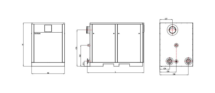
| MODEL | W (mm) |
H (mm) |
L (mm) |
C1 (mm) |
C2 (mm) |
C3 (mm) |
C4 (mm) |
C5 (mm) |
C6 (mm) |
C7 (mm) |
|---|---|---|---|---|---|---|---|---|---|---|
| CELL-CONDENSE-SS 290 | 750 | 1473 | 1585 | 197 | 340 | 1293 | 225 | 428 | 630 | 537 |
| CELL-CONDENSE-SS 420 | 1250 | 1613 | 1545 | 188 | 787 | 1415 | 373 | 625 | 1082 | 480 |
| CELL-CONDENSE-SS-560 | 1250 | 1613 | 1545 | 188 | 787 | 1415 | 373 | 625 | 1082 | 480 |
| CELL-CONDENSE-SS-700 | 1250 | 1613 | 2090 | 195 | 795 | 1415 | 373 | 625 | 1082 | 480 |
| CELL-CONDENSE-SS-840 | 1250 | 1613 | 2090 | 195 | 795 | 1415 | 373 | 625 | 1082 | 480 |
| CELL-CONDENSE-SS-1000 | 1250 | 1613 | 2635 | 207 | 795 | 1418 | 373 | 625 | 1082 | 480 |
| CELL-CONDENSE-SS-1120 | 1250 | 1613 | 2635 | 207 | 795 | 1418 | 373 | 625 | 1082 | 480 |
| CELL-CONDENSE-SS-1260 | 1250 | 1613 | 3310 | 220 | 756 | 1390 | 370 | 625 | 1080 | 480 |
| CELL-CONDENSE-SS-1400 | 1250 | 1613 | 3310 | 220 | 756 | 1390 | 370 | 625 | 1080 | 480 |
| CELL-CONDENSE-SS-1540 | 1250 | 1613 | 3860 | 220 | 756 | 1390 | 370 | 625 | 1080 | 480 |
| CELL-CONDENSE-SS-1680 | 1250 | 1613 | 3860 | 220 | 756 | 1390 | 370 | 625 | 1080 | 480 |